Understanding the Operation and Settings of the
AirGraver and Handpiece (Foot Control Model)
 Although
it is good to experiment with the controls (working with them can provide
a greater depth of understanding on how to best set the tool for
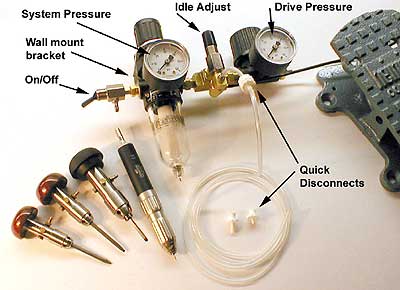
individual engraving needs),. in general, it is best to leave the left
regulator (system pressure) set at 50 to 60 PSI. The regulator on the
right (drive pressure) governs how much air goes to the handpiece when the
pedal is pressed all the way down. Using a practice plate, try setting the
drive pressure to 50 PSI, and take several cuts. Then set it at 35 PSI,
and take several more cuts. Try it again at 20, 10, and 5 PSI. (note: The
stroke length ring on the handpiece will need to be set to a short stroke
to see the benefit of 5 to 10 PSI). The only reason to set the PSI down
lower is for fine shading cuts, but even this might not be needed. It is
really only necessary if the operator desires more pedal travel throughout
the lower PSI range. The needle valve (labeled "idle adjust" in the
picture above) between the two regulators is for setting the speed of the
idle. Set it so it is very fine, but not so fine that the idle stops
easily between engraving cuts. Generally, engravers leave the regulator at
35 PSI for fine to heavy work, and this is fine - but be aware that it can
be adjusted if desired.
Although
it is good to experiment with the controls (working with them can provide
a greater depth of understanding on how to best set the tool for
individual engraving needs),. in general, it is best to leave the left
regulator (system pressure) set at 50 to 60 PSI. The regulator on the
right (drive pressure) governs how much air goes to the handpiece when the
pedal is pressed all the way down. Using a practice plate, try setting the
drive pressure to 50 PSI, and take several cuts. Then set it at 35 PSI,
and take several more cuts. Try it again at 20, 10, and 5 PSI. (note: The
stroke length ring on the handpiece will need to be set to a short stroke
to see the benefit of 5 to 10 PSI). The only reason to set the PSI down
lower is for fine shading cuts, but even this might not be needed. It is
really only necessary if the operator desires more pedal travel throughout
the lower PSI range. The needle valve (labeled "idle adjust" in the
picture above) between the two regulators is for setting the speed of the
idle. Set it so it is very fine, but not so fine that the idle stops
easily between engraving cuts. Generally, engravers leave the regulator at
35 PSI for fine to heavy work, and this is fine - but be aware that it can
be adjusted if desired.
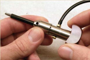
Length and speed of stroke adjustment ring on the
AirGraver handpiece
The stroke
length setting of the adjusting ring on the handpiece can be compared to
using a conventional hammer. To get light taps with a hammer, a short back
stroke is used. Longer back strokes allow a hammer head to increase in
velocity with the forward stroke. The length of stroke adjust ring in the
AirGraver handpiece alters the porting and anvil together to give longer
and shorter piston strokes.
Depending
on the direction you turn it, the adjusting ring actually moves the anvil
in the AirGraver closer to (or further from) the oscillating piston. This
alters the speed of the impacts and the travel distance of the piston.
When trying various PSI settings with the controller as described above,
also try various settings of the adjust ring. Try cutting a few lines with
each setting on a practice plate.
The
throttle will not need to be moved as far for a short stroke to begin
impacting as it will for a long stroke. If the drive PSI is set fairly
low, along with a long stroke, the throttle pedal will need to be moved a
great distance before actual impacts begin. Thus, for a longer stroke
setting on the adjusting ring, the regulator should generally be set to 30
PSI or more Long strokes will have more impacting power than shorter
strokes, and more PSI is needed for the longer stroke.
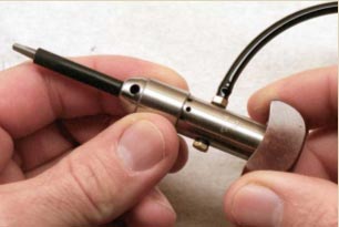
To adjust
the mechanism, simply turn the ring. When adjusting, a reference to the
stroke setting can be made by viewing the underside of the AirGraver.
There are three holes on the bottom of the body of the tool. Reference may
be made depending on how many or how much of the holes are covered by the
adjustment ring. If all the holes are exposed, the setting is for the
longest stroke, and slowest, hardest-hitting impacts per minute. Adjusting
the ring so that all the holes are closed sets the tool for the shortest,
fastest, and softest impacts per minute. Some resistance when rotating the
ring will be felt when reaching either the shortest or longest extreme.
Caution: We do not recommend operating the tool against
the adjustment stop of the longest stroke setting. To set the tool for the
longest stroke, back off the ring approximately ½ turn from where the stop
is felt. Alternatively,, the ring can be turned so that all the holes are
exposed, and not any further. This will be approximately ½ turn from the
resistance stop. Probably no harm would be caused if the tool were to be
operated hard against this stop, but we advise against it. If desired, the
handpiece may be run against the stop of the shortest stroke setting
without concerns.
The idle will always return to the same oscillation speed throughout the
impact length of stroke settings. The impact adjusting mechanism only
adjusts porting along with the anvil position in the tool during impact,
and it will not affect the idle.
Suggested settings for various tasks
Long stroke:
larger scroll outlining, large bright cut work, stippling background,
background removal using a flat graver, channel stone setting.
Medium stroke:
scroll outlining, larger scroll shading work, finer bright cut work,
bulino stippling with a punch.
Short stroke:
shading, fine scroll outlining, scene engraving, pearl or ivory line
engraving
Various interesting settings
The needle
valve used to set the idle can be used to control the impacting of the
tool without the use of the throttle. This is sometimes helpful for
stippling background. Because background stippling does not require a
variable amount of impact power, the handpiece can be set with the idle
adjust needle valve so that the handpiece is impacting continually. To do
this, turn the idle needle valve counter clockwise until the handpiece is
impacting at the desired power. If pausing work and wishing to leave the
tool set up as is, the on/off toggle can be used to turn the tool on or
off.
Another interesting and helpful variation is to again use the needle valve
again for a task without the use of the throttle. By carefully setting the
stroke length with the amount of idle air, it is possible to have the tool
begin impacting by itself when the graver point is set against the work.
This is useful if there are a lot of short fine lines to be cut. Set the
tool to achieve this by first setting the length of stroke desired. This
setting works best at the shorter stroke settings. With the adjusting ring
set fairly short, and the handpiece in hand and orientated to an engraving
position (but without the point against the surface of the work), slowly
unscrew the idle needle valve to allow the idle to increase. Unscrew it
until the handpiece just begins impacting, and then turn the needle valve
knob the other way a very small amount to slow the idle down a little. The
object is to have the tool idling fast enough that it is just on the verge
of starting to impact. With this setting, set the graver point against the
work. The handpiece will begin impacting lightly and cutting. This setting
is generally only good for fine line engraving in one weight of line. The
stroke length can be increased with the adjust ring, and then turning the
idle up to provide more power when the tool is set down, but if this is
done too much, it will cause the tool to vibrate in the hand and will make
it difficult to set the point down exactly where desired. Therefore,
experiment with this for just the finest of lines, as the faster idling
speed or vibration is eliminated.
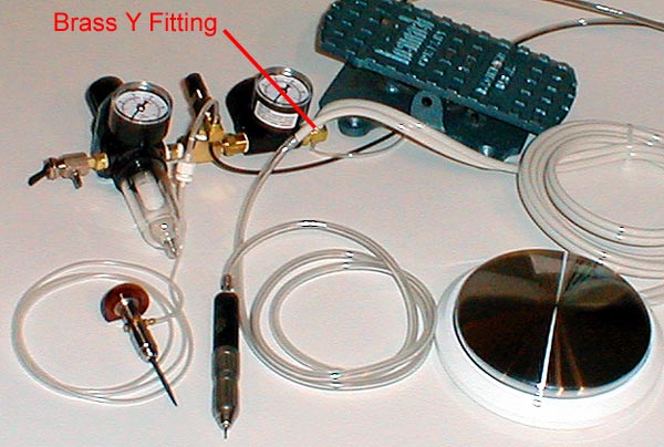
Attaching the Rotary Disc Foot Control
The rotary
foot control is supplied with a brass Y fitting. To install it. unscrew
the barb fitting on the right side of the regulator, and replace it with
the Y fitting. Screw the supplied larger barb in one leg of the Y, and the
smaller barb into the other leg. The clear teeter-totter foot control
tubing attaches to the small barb, while the rotary disc foot control
pedal tubing attaches to the large barb. Look closely at the rotary disc
foot control tubing. One of the lines has a rib running lengthwise on the
tubing. This line supplies incoming air to the disc foot pedal. This is
the line that attaches to the large barb on the Y fitting. The other line
of the disc foot pedal is to be attached directly to the handpiece tubing
running to the rotary handpiece. The Presto NSK rotary's factory
recommended maximum pressure setting is 35 PSI. Therefore, during the
rotary tool's use, set the drive regulator (the regulator on the right) at
35 PSI or lower. Other rotary handpiece maximum PSI settings may be
different than the Presto NSK handpiece, so check the manufacturer's
recommendation.
If
using the AirGraver handpiece at higher than the 35 PSI setting, the drive
pressure may be left at high rather than readjusting the regulator back
and forth. Listen to the sound of the rotary tool and be careful not to
push the pedal to maximum power. To determine the sound to listen for, set
the drive pressure at 35 PSI and floor the tool. Do not allow this sound
to increase.

.png)